ESET 462 Final Project
Portable Safety Light
This project is aimed towards creating a motion-activated
portable safety light that demonstrates a basic feedback control design using an Elegoo Uno R3 and a photo-resistor. The system automatically adjust its brightness based on the available light. The practical application is that it can illuminate any space to deter any unwanted presences and for easier traversability. To accomplish the aforementioned, the system uses a feedback signal for a closed loop control.
Physical Structure
The enclosure was modeled using Fusion 360 and 3D printed using PLA filament.
The enclosure has been divided into two distinct parts - the front face and the back face - to facilitate easier access and replacement of the battery, if required.
The front face houses a Photo-Resistor, HC-SR501 PIR Motion Sensor, Chanzon 10W LED Chip, and LED Lens Optical Glass.
The back face houses an Elegoo Uno R3, Mini Breadboard, IRF520 MOSFET Driver Module, 9V Battery, and a Single-Joint Toggle Switch.


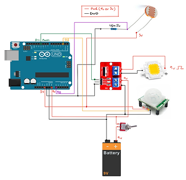
Wiring Diagram
To the left is the wiring diagram, illustrating that the entire system is powered by a 9V battery. To conserve energy, a toggle switch has been integrated into the system, allowing the user to choose when to use the light. The 9V battery is connected to the Elegoo Uno R3, which utilizes its internal voltage regulator to reduce it to 5V. This 5V power source is then utilized for the remaining components.
Key Components
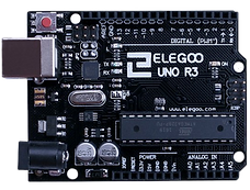
The Elegoo Uno R3 is employed for processing and decision-making of the collected data. It is equipped with both analog and digital input/output pins, which are essential for the system.
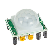
With its 120-degree field of view and capacity to detect motion up to 7 meters, the HC-SR501 PIR Motion Sensor identifies objects that are in close proximity to the system.
To regulate the intensity of an LED chip, a Sparkfun Photoresistor is employed to measure the amount of ambient light available and generate an unprocessed analog value.
The IRF520 MOSFET Driver Module enables the control of high DC loads using a single digital pin from a micro-controller. In this case, a pulse width modulation (PWM) signal is used to adjust the brightness of an LED.
The Chanzon LED chip has the ability to provide up to 10 Watts of power and a perceived power of 900-1000 LM (luminous flux), ensuring that the system is capable of illuminating a designated area effectively.


Software Flowchart
To create the program, the Arduino IDE is utilized. Whenever the motion sensor detects any motion, it will send a LOW or a HIGH signal. Based on this signal, the system will turn on the LED with the brightness level that has been adjusted.
In order to modulate the LED brightness, the raw analog value from the photo-resistor is inverted and then mapped to a range of values which produces a gradient effect of the LED's brightness.
Closed Loop Control with Feedback Signal
Displayed on the right is the fundamental closed loop configuration of the system. The input comprises of a reading from the photo-resistor which is subsequently processed by the Elegoo Uno R3 and MOSFET driver to illuminate the LED. The system employs a feedback signal and proportional gain to suitably adjust the LED brightness.

Complete Physical Model


